
ARMY TM 9-6115-673-13&P
AIR FORCE TO 35C2-3-512-1
(2) If removed, position thrust plate (6) and governor lever (5) on governor shaft.
(3) Secure governor lever (5) to governor shaft with new pin (4).
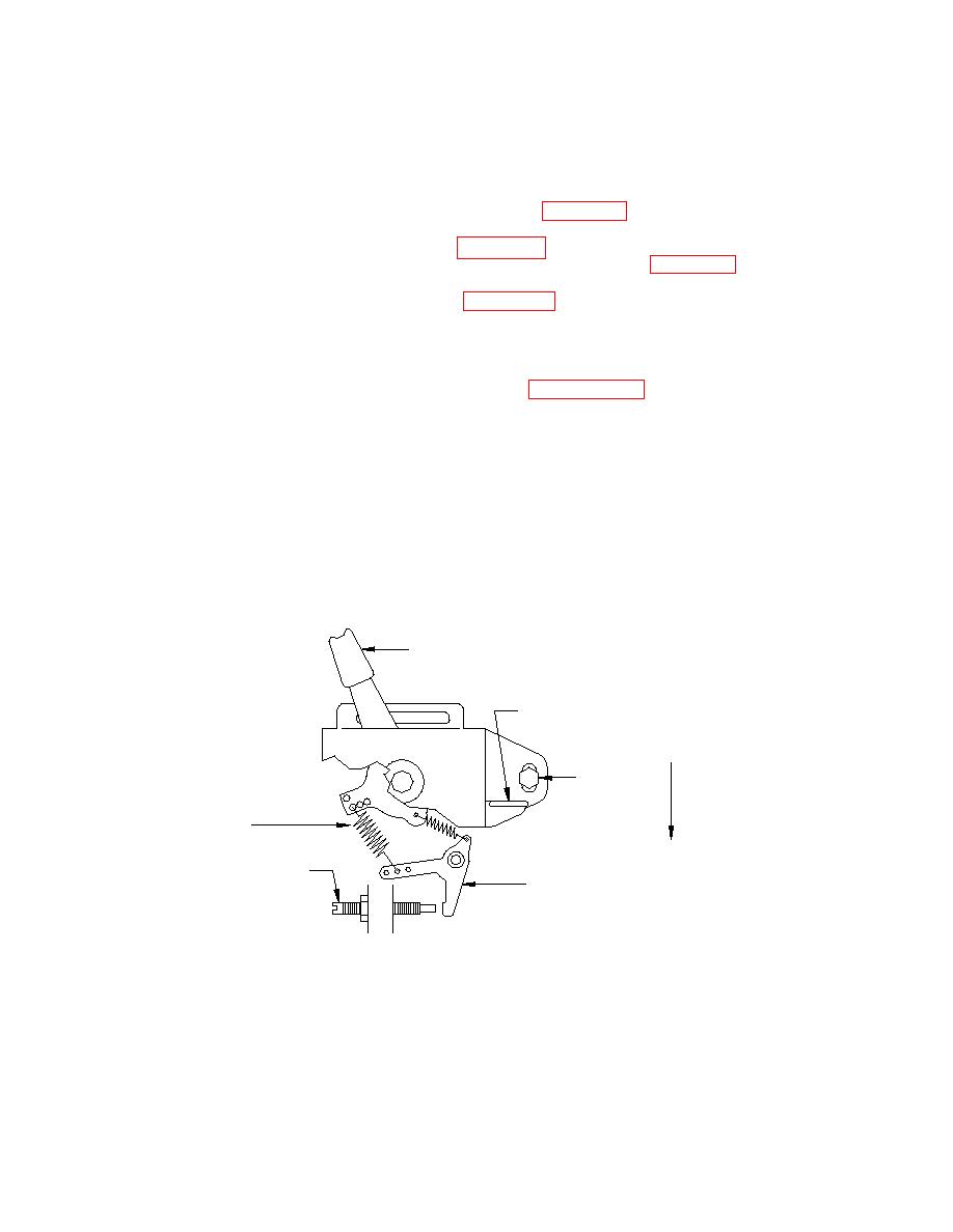
(4) Attach springs (9 and 10) to regulator bracket (3) ensuring spring (9) is connected
to lower outer hole on run lever, refer to Figure 4-53.
(5) Connect springs (9 and 10, Figure 4-52) to governor lever (5). Ensure spring (9) is
connected in middle hole of governor lever arm, refer to Figure 4-53.
(6) Install regulator bracket (3, Figure 4-52), with STOP lever attached, on cylinder
block with bolt (2) and bolt (1).
(7) Connect LOP engine shutdown cable to STOP lever and regulator bracket (3).
Pinch ears on red STOP lever to capture LOP shutdown cable. Adjust LOP
shutdown cable as necessary, refer to paragraph 4.50.d.
regulator bracket and move regulator bracket down to increase speed (frequency)
or up to decrease speed.
NOTE
Breaking seal on screw (8) to remove or adjust voids engine
warranty.
RUN
LEVER
STOP LEVER
INCREASE
PIVOT
FREQUENCY
SCREW
GOVERNOR
SPRING
ADJUSTMENT
SCREW
GOVERNOR
LEVER
