
TM 55-6115-491-40
Note
Do not reverse armature rotation when removing sandpaper.
r.
(4) Remove the sandpaper and blow out
Position the end bell mounting (53),
all carbon dust with dry, clean compressed air. Proceed
permanent magnet generator stator (52), and end bell
with brush run-in as described in paragraph 4-6.
(48) on the permanent magnet end of the generator;
secure with four bolts (49), lock washers (50), and flat
washers (51).
Note
Diodes must be positioned so that they are aligned with the AC terminal block (71).
s. Position the diode semiconductors (42) on
plastic washers (47) in dielectric fluid (item 4, table 2-3).
Drain thoroughly before installation. Secure the diodes
the flange of the end bell (48) so that they will alternate
with plastic washers (47), mica washers (46), flat
with the diode semiconductors 140) that are assembled
washers (45), lock washers (44), and nuts (43). Figure 3-
to the lead assembly (34). (Refer to figure 3-6.1 Dip all
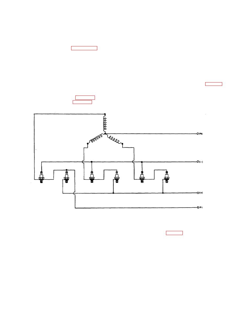
6. PM Generator Wiring Diagram.
diode-mounting mica washers (46, figure 3-2) and
Figure 3-6. PM Generator Wiring Diagram.
t.
Position the lead assembly (41) and lead
(38), flat washers (37), lock washers (36), and nuts (35).
Be sure that the nonmetallic washers are dipped in
assembly (34) on the end bell flange so that the diodes
dielectric fluid (item 4, table 2-3) and are drained before
(40) of lead assembly (34) extend through the lug
assembly.
terminals of lead assembly (41). Secure the diodes to
the end bell with plastic washers (39), mica washers
Caution
Diodes are heat sensitive. If it is necessary to solder the leads to the diodes, always
use a heat dissipator between the solder joint and the diode to prevent heat damage to
the diode.
3-18
