
TM 55-6115-491-40
4-6. BRUSH RUN-IN.
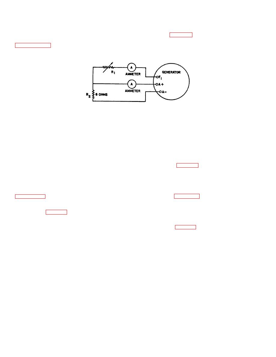
a. After new brushes have been installed and
between terminals F 1 and A+; also insert a fixed
preliminary seating procedures completed (refer to
resistance (R 2) of 6 ohms (400 watts) between
terminals A+ and A-.
brush run-in stand and complete connections as
Figure 4-3. Brush Run-in Connection.
b.
With the variable resistance between
recheck to make sure the field current adjustment has
been maintained.
terminals F 1 and A+ adjusted to permit a flow of 3/4
c. Check the output voltage across each phase.
ampere in the exciter shunt field circuit, operate
The T1 -T2, T 2 -T3'and T3 -T1 voltage shall be 200 1 volts.
generator at a speed of 6, 000 RPM. Cooling air should
Commutation shall be black.
be provided. Continue operation until the contact surface
d. After checking to assure that output is within
of each brush is seated 100 percent in the direction of
rotation and at least 90 percent in the axial direction.
the required limits, the position of the brush support must
c. Blow out all carbon dust and proceed with
be locked by drilling the stator housing and inserting a
performance testing.
spring pin (75, figure 3-1). There are two slots machined
in the lip of the bearing support that engages the stator
4-7. PERFORMANCE TESTS.
housing. If both of these slots are aligned with or are
4-8. AC Generator Exciter Field Current Test.
partially aligned with a hole in the stator housing as a
a. With the generator at ambient temperature,
result of previous pinning, the brush support must be
not warmed up from operation, operate the generator at
removed and a new slot will have to be machined in the
8, 000 RPM no-load, with the cooling conditions cited in
lip. Refer to figure 4-4 for slot dimensions. After
machining, reestablish the position of the brush support
b. Check the exciter field current. It must be 0,
to provide the exciter field current indicated above.
14+0.01 ampere. If it is not within this range, loosen the
e. Drill a 0.124to 0.128-inch radial hole 0.542 to
eight nuts (67, figure 3-1) and retightd two opposing nuts
0.562 inch deep in the stator housing so that it is aligned
until they are just snug. Tap the brush support to rotate it
with the slot in the lip of the brush support. Drive in the
slightly until the field current is in the required range.
spring pin (75, figure 3-1) to lock the position of the brush
Tighten the nuts to secure the adjustment and
support.
4-3
