TM 55-6115-491-40
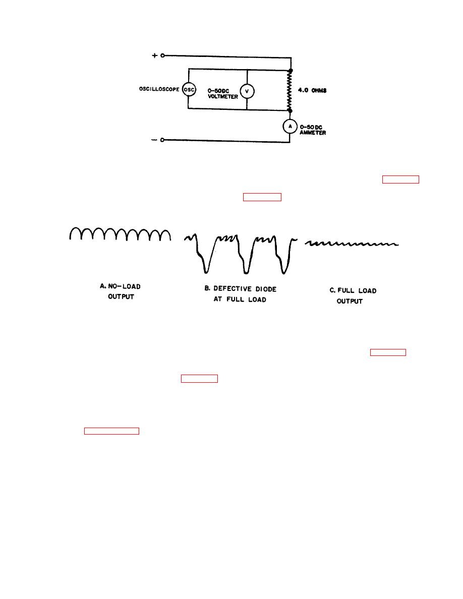
Figure 4-5. PM Generator Full-load Voltage Test.
b. Operate the generator at 7, 000 RPM for
d. With an oscilloscope, check the waveform of
about five minutes to allow the temperature to stabilize.
the DC output. It shall be as shown in C, figure 4-6. If a
c. With the generator operating at 7, 000 RPM,
check the DC output voltage. It shall be 19.0 volts
minimum.
Figure 4-6. Waveforms Produced by PM Generator Output.
4-12. AC Generator Phase Rotation Test.
balanced 3-phase load, and 0.75 power factor. Voltage
a. Operate the generator at 8, 000 RPM no load,
regulator and control panel are to be connected to
generator during this test as shown in figure 4-2.
driving the rotor in a counterclockwise direction, facing
b. Operate generator under these conditions
drive end.
b. With a phase sequence indicator connected
until the AC stator stack temperature does not increase
more than 2 F (1.1 C I in five minutes. Record line
to the generator output terminals as shown in figure 4-2,
voltages and current, exciter armature voltages and field
the phase rotation sequence shall be T1, T2 T3
current, air inlet temperature,
AC stator stack
4-13. HEATING, COMMUTATION, AND SYMMETRY
temperature and commutation. Cummutation shall be
OF CONSTRUCTION TEST .
such that there is no more than pin point arcing along the
a. Using a suitable clamp, attach thermocouple
edges of the brushes. AC stator stack temperature shall
to generator housing. With cooling air supplied in
not exceed 3250 F (1630 C). Exciter field current shall
accordance with paragraph 4-3, and with a means of
be 0.75 ampere maximum. KVAR shall be 13.25 F0.75.
determining speed within : 1 percent, operate generator
KW shall be 15.0 : 0.75.
at 8, 000 : 80 RPM, 208 volts, 55.5 amperes with
c. For symmetry of construction, determine
unbalance which is defined as 100 times the
4-5


