
TM 55-6115-491-40
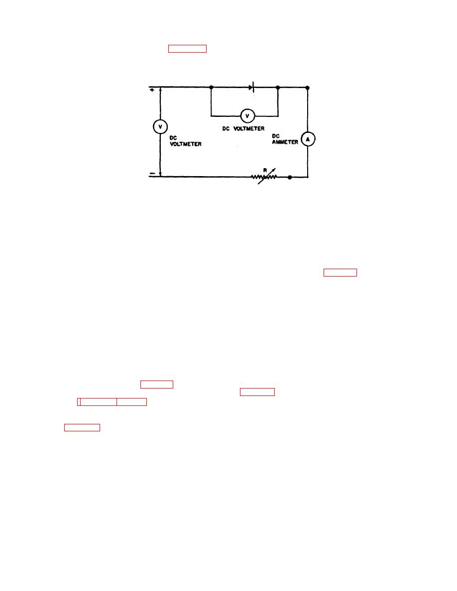
b. Connect the diode as shown in figure 3-5 to
voltage drop across the diode should be less than 1.5
volt DC at 770F (250 C). Replace the diode if it fails to
check forward current flow. Increase the DC input
conform to these requirements.
voltage until the ammeter indicates 3 amps. The
Figure 3-5. Diode Forward Current Test.
b. Position the assembled brush boxes on the
3-29. MODIFICATION CRITERIA.
bearing support (46) and brush holder insulations (37) on
3-30. Comply with the following instructions in order to
the bearing support; secure with the bolts (32), washers
control configuration of generator Part No. 31220-002.
(33), plates (34), insulation (35), and bushing insulator
a. If shaft Part No. 31220-1053 is installed,
(36). Tighten the bolts to 17 to 20 inch-pounds.
and if the letter "S" is already on the identification plate
c. Position the brush holders (25) and brush
following the serial number, obliterate the letter "S".
holder insulations on the bearing support using the
b. If shaft Part No. 31220-1160 is installed,
aligning tool indicated in table 2-2. Secure by installing
assure that the letter "S" is stamped on the identification
the bolts (26), washers (27), plates (28), insulations (29),
plate following the numerical serial number.
and bushing insulator (30). Tighten the bolts to 17 to 20
c. If bearing Part No. 07-111424 is replaced
inch-pounds.
with bearing Part No. 07-111438 and if the letter "B" is
d. Install the electrical leads (17 through 19)
not already on the identification plate after the serial
and the wire jumper (20) that interconnect the brush
number, stamp the letter "B" onto the plate.
holders.
d. If it is necessary to install bearings Part No.
e. Position the exciter board (8), spacer
07-11424 due to the non-availability of bearing Part No.
gasket (15), and standoff insulator (16) on the bearing
07-111438, and if the letter "B" is already on the
support (46); secure by installing the terminal sleeves
identification plate, either replace the identification plate
(14), insulator bushings (13), flat washers (12), bolts
or obliterate the letter "B" from the present plate.
(11), washers (10), and nuts (9). The terminal board
3-31. LUBRICATION.
must be positioned so that A- faces the anti-drive end.
3-32. Lubricate the parts of the generator prior to
f.
If they were removed, install new studs (70,
reassembly using items 2 and 3 of table 2-3.
3-33. REASSEMBLY.
(69) that were removed from the terminal board (71).
3-34. Refer to figures 3-1 and 3-2 and reassemble the
g. Position the assembled brush support
generator as follows:
assembly (661 on the stator housing (74). Connect the
a. Assemble the brush boxes (items 39
exciter terminal board leads. Connect the DC stator
through 45, figure 3-2).
leads to the brush holder. Secure with eight nuts (67)
and washers (68).
3-16
