TM 55-6115-491-40
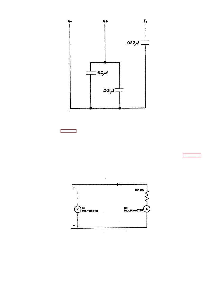
Figure 3-3. Capacitor, Schematic Diagram.
3-25. Permanent Magnet Rotor.
of the stator frame. No continuity shall exist. Replace if
3-26. Magnetize a weak or new permanent magnet
grounded.
c. Check dielectric strength of stator insulation
rotor using a magnet charger (table 2-2). Use maximum
by applying 250 volts (RMS) between each winding lead
magnetizing force and magnetize so that adjacent poles
and ground for one minute. There shall be no indication
have the opposite polarity. Do not use a keeper on the
of insulation breakdown. Replace the stator if
magnet after processing.
3-27. Permanent Magnet Stator.
breakdown is indicated.
3-28. Diode Semiconductor Devices.
a. Using test lamp described in paragraph 3-
a. Connect the diode as shown in figure 3-4 to
16, check continuity of the permanent magnet stator.
check reverse current flow. Be sure to observe polarity.
Continuity must exist between each pair of stator leads.
Increase the DC input voltage until the voltmeter
Replace stator if continuity fails to exist.
b. Using a test lamp, check for grounds
indicates 200 volts DC. The current at 77 F (250 C)
should not exceed 0.5 milliamperes DC.
between the stator leads and an unpainted portion
Figure 3-4. Diode Reverse Current Test.
3-15


