
TM 9-6115-730-24
0083
REPROGRAMMING OR VERIFYING DVR PARAMETERS - Continued
13. Press Function
key on DVR once to switch back to the parameter number.
once to change to next parameter number per Table 2.
14. Press up arrow key
15. Keep repeating from step 7, entering or viewing parameter data from Table 2, until all parameter data is
entered or verified to be correct.
16. Press Function
key on DVR once to display data for parameter :90.
or down arrow key
to set the data for parameter number :90 to any
17. Press and hold up arrow key
number but 0009 to lock the DVR. DVR will not stay locked when ENGINE CONTROL switch is switched
from either COOL DOWN/STOP to OFF/RESET and back to COOL DOWN/STOP or from COOL
DOWN/STOP to MANUAL START.
18. If the generator set is not to be used, set ENGINE CONTROL switch to OFF/RESET, set DEAD CRANK
SWITCH to OFF, and set Battery Disconnect Switch to OFF.
END OF TASK
REPROGRAMMING GSC SETPOINTS FOR VOLTAGE AND FREQUENCY CHANGE
1. Set Battery Disconnect Switch to ON.
2. Set DEAD CRANK SWITCH to NORMAL.
3. On EMCP, set ENGINE CONTROL switch to COOL DOWN/STOP.
4. Select programming data for GSC from Table 3 for desired output voltage and desired frequency.
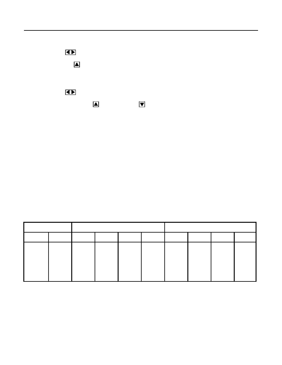
Table 3. 200 kW TQG GSC Programming Setpoints.
DESIRED OUTPUT
OP5-0
OP5-1
VOLTS
HERTZ
P028
P029
P030
P031
P114
P117
P120
P123
120/208
60
208
694
200
60
63
66
57
54
120/208
50
208
576
166
50
53
55
48
45
240/416
60
416
347
200
60
63
66
57
54
240/416
50
416
288
166
50
53
55
48
45
