TM 9-6115-650-14&P
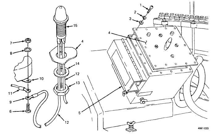
Figure 4-10. Indicator Light and Wire Assembly Replacement.
(2) Installation.
(a)
(b)
(c)
(d)
(e)
(f)
Pull terminal (9) off each indicator light wire (12).
Feed wires (12) through hole in cover (4) and fit light housing (15) in hole.
Slide nut (13) and Iockwasher (14) over both wires (12), thread onto housing (15) on inside of cover
(4) and tighten.
Crimp one terminal (9) onto each wire (12).
Position terminal (9) of each indicator light wire (12) against underside of switch terminal (10).
Position terminal of power cable wire (11) against terminal of indicator light wire. Insert screw (6) up
through wire terminals and switch terminal. Install star washer (8) and nut (7) on screw and tighten
against switch terminal.
Position cover (4) on switch box (5) and secure with 16 screws (1), 16 Iockwashers (2) and 16 flat
washers (3).
c.
Switch to Load Terminal Wire Replacement. (See figure 4-11.) There are three wires connecting the
switch to the load terminals. When attaching wires, refer to the schematic (figure 4-7) inside the switch box and to
the identification bands on the wires.
4-23