ARMY TM 9-6115-639-13
AIR FORCE TO 35C2-3-386-51
MARINE CORPS TM 10155A-13/1
4-19. OPERATOR SWITCH MAINTENANCE - cont.
7.
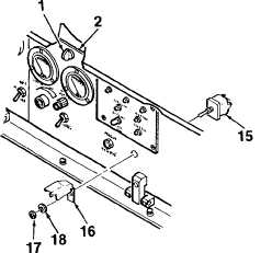
Remove BATTLE SHORT switch (15) and
switch guard (16) from control panel (2) by
removing attaching nut (17) and lockwasher (18).
B. INSPECTION.
1.
Inspect switches for obvious damage. Check for
corrosion or evidence of electrical short.
2.
Inspect electrical wiring for cuts, crimps, bare
wire, or other damage. Ensure connectors are
securely attached.
3.
Remove and replace any component that is
damaged to the extent that it will effect the safe
operation of the generator set.
C. INSTALLATION.
1.
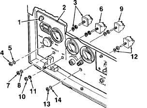
Install AUX FUEL switch (3, Figure 4-10) onto
control panel (2) using attaching nut (4) and
lockwasher (5).
2.
Install PREHEAT switch (6) onto control panel
(2) using attaching nut (7) and lockwasher (8).
3.
Install START / RUN / STOP switch (9) onto
control panel (2) using attaching nut (10) and
lockwasher (11).
4.
Install CIRCUIT INTERRUPTER switch (12)
onto control panel (2) using attaching nut (13)
and lockwasher (14).
5.
Remove BATTLE SHORT switch (15) and
switch guard (16) from control panel (2) by
removing attaching nut (17) and lockwasher (18).
6.
Connect electrical wiring to the rear of switches
(3, 6, 9, 12, 15).
7.
Close control panel (2) and lock in place using
quarter-turn fasteners (1).
Figure 4-10. Operator Switches
(Sheet 2 of 2)
4-40