ARMY TM 9-6115-639-13
AIR FORCE TO 35C2-3-386-51
MARINE CORPS TM 10155A-13/1
4-15. FUEL LEVEL GAUGE MAINTENANCE
This task covers removal, inspection, and installation.
INITIAL SETUP
Tools:
Equipment Condition:
Tool Kit, General Mechanic’s Automotive
Generator set shut down (Para. 2-9)
(Item 2, App. B, Sect. III)
Battery cables disconnected
Cable disconnected for SLAVE RECEPTACLE
A. REMOVAL.
1.
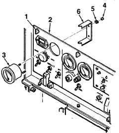
Turn quarter-turn fasteners (1, Figure 4-6) to
unlock and open control panel (2).
2.
Tag and disconnect electrical wiring from the rear
of FUEL LEVEL gauge (3).
3.
Remove FUEL LEVEL gauge (3) from control
panel (2) by removing two nuts (4), lockwashers
(5), and bracket (6).
B. INSPECTION.
1.
Inspect FUEL LEVEL gauge for corrosion and
obvious damage. Inspect for broken glass.
2.
Inspect electrical wiring for cuts, crimps, bare
wire, or other damage. Ensure connectors are
securely attached.
3.
Remove and replace any component that is
damaged to the extent that it will effect the safe
operation of the generator set.
Figure 4-6. FUEL LEVEL Gauge
C. INSTALLATION.
1.
Install FUEL LEVEL gauge (3, Figure 4-6) onto
control panel (2) using two nuts (4), lockwashers
(5), and bracket (6).
2.
Connect electrical wiring to the rear of FUEL
LEVEL gauge (3).
3.
Close control panel (2) and lock in place using
quarter-turn fasteners (1).
4-35