ARMY TM 9-6115-639-13
AIR FORCE TO 35C2-3-386-51
MARINE CORPS TM 10155A-13/1
4-20. EMERGENCY STOP SWITCH MAINTENANCE
This task covers removal, inspection, and installation.
INITIAL SETUP
Tools:
Equipment Condition:
Tool Kit, General Mechanic’s Automotive
Generator set shut down (Para. 2-9)
(Item 2, App. B, Sect. III)
Battery cables disconnected
Cable disconnected for SLAVE RECEPTACLE
A. REMOVAL.
1.
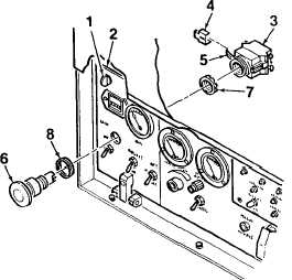
Turn quarter-turn fasteners (1, Figure 4-11) to
unlock and open control panel (2).
2.
Tag and disconnect electrical wiring from the rear
of EMERGENCY STOP switch (3).
3.
Remove yellow locking tab (4) from side of
switch (3). Rotate lever (5) on switch to unlock
position and remove switch from rear of control
panel (2).
NOTE
Observe orientation of push button (6)
before removing to aid in assembly.
4.
Remove push button (6) from control panel (2) by
removing locknut (7) and gasket (8).
B. INSPECTION.
1.
Inspect
EMERGENCY
STOP
switch
for
corrosion and obvious damage. Inspect electrical
connectors for damage and evidence of short.
2.
Depress switch shaft to check for proper
operation. Switch must depress and reset
smoothly.
3.
Inspect electrical wiring for cuts, crimps, bare
wire, or other damage. Ensure connectors are
securely attached.
Figure 4-11. EMERGENCY STOP Switch
(Sheet 1 of 2)
4-41