ARMY TM 9-6115-673-13&P
AIR FORCE TO 35C2-3-512-1
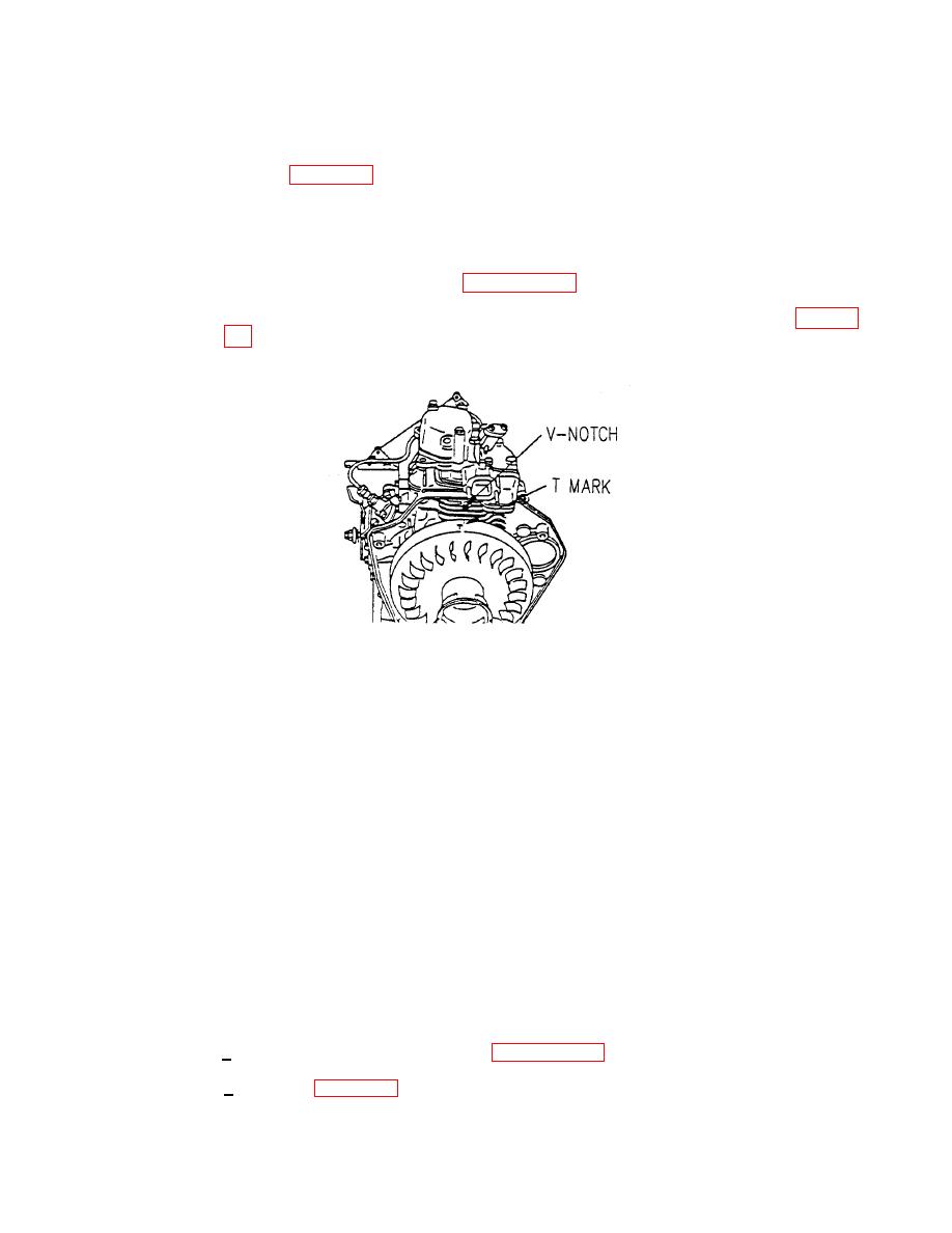
If two sets of timing marks are found, position the flywheel so that looking from the
flywheel side, one set of timing marks at the 12 o'clock position are in line with the
V notch line (Figure 5-14) on the cylinder body fin and the second set of marks are
at the 3 o'clock position (90 degrees to the right). When the flywheel is in this
position, the correct timing marks are visible at the V notch. Time the engine in
accordance with the procedure below.
(a) Remove cooling fan cover, refer to paragraph 4.53.b.
(b) Align the T position mark on the flywheel with the V notch on the cylinder body fin (Figure 5-
(c) If installed, disconnect pressure fuel line from fuel injection pump and fuel injector, and move
aside.
(d) Set start lever to RUN.
(e) Turn the flywheel counterclockwise approximately 30o, then turn flywheel clockwise back to T
mark, and ensure fuel moves in fuel injection pump. If there is no fuel movement, turn flywheel
one full turn clockwise and realign T mark.
(f) Turn flywheel counterclockwise approximately 30o from T, then turn flywheel clockwise until fuel
just begins to move in fuel injection pump. Record angle before T that fuel begins to move.
Each mark on flywheel is equal to 5o.
(g) Repeat step (f) three or four times to verify angle. The correct injection timing angle is 17o before
T.
(h) Adjust injection timing:
1 Remove fuel injection pump, refer to paragraph 5.15.a.
less than 17o. Each 0.0039 in. (0.1 mm) shim changes timing by 1o.


