
ARMY TM 9-6115-673-13&P
AIR FORCE TO 35C2-3-512-1
d. Adjustment.
(1) Check fuel injection volume limitation setting:
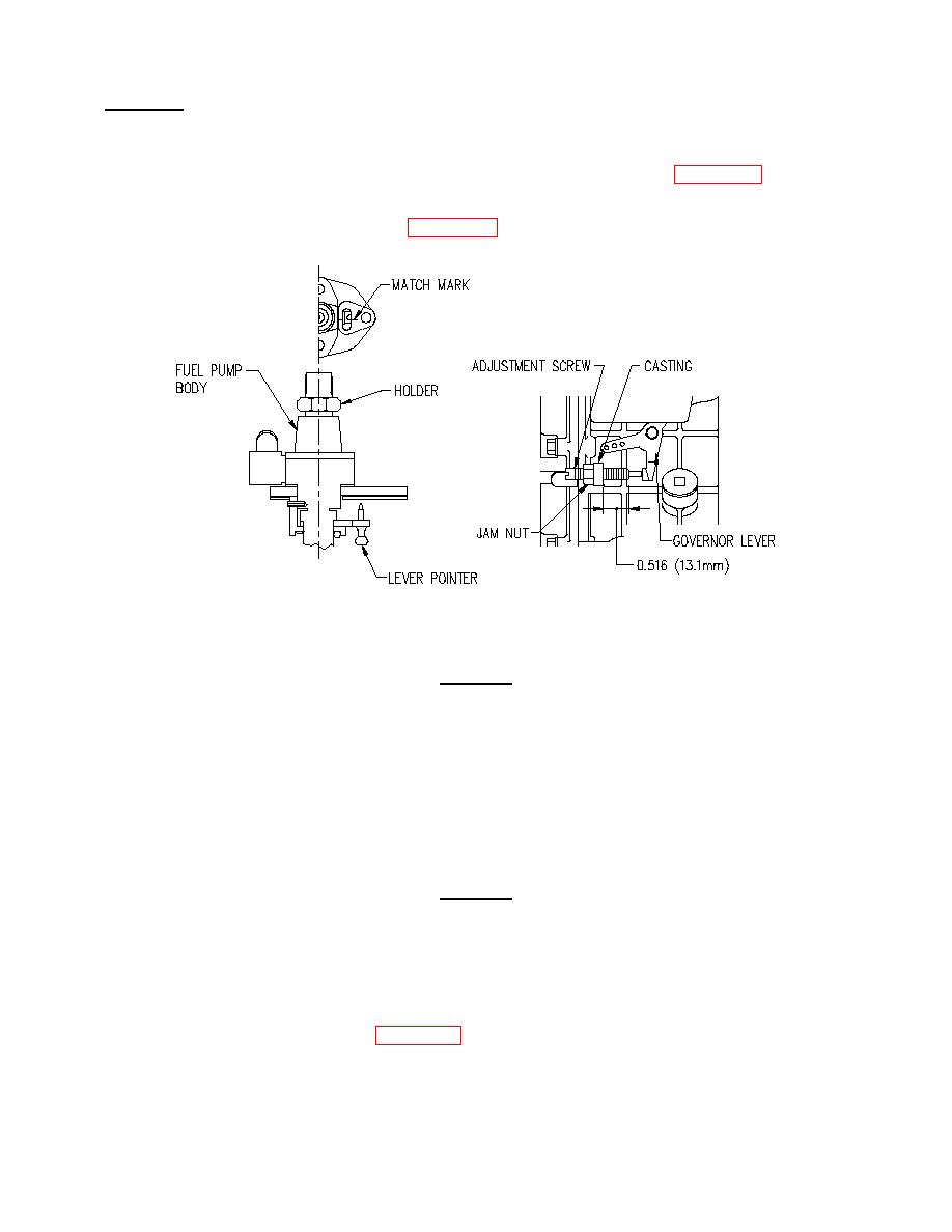
(a) Ensure that governor linkage and spring position is properly set (Figure 5-12).
(b) Measure length of threaded portion of fuel limitation adjustment screw extending forward of
adjustment screw casting (Figure 5-13). Measurement should be 0.516 in. (13.1 mm).
CAUTION
Fuel limitation adjustment screw is factory set and sealed. Any adjustment of
screw during warranty period will void warranty.
(c) If necessary, break seal on fuel limitation adjustment screw, loosen jam nut, and adjust screw to
achieve measurement stated in step (b).
(d) Tighten jam nut and install new seal.
(2) Check fuel injection timing:
CAUTION
Two sets of timing marks may be stamped on the flywheel. These marks may be
on engines with Serial Numbers 39795 and above. The following procedure must
be followed:
First visually confirm that the flywheel has two distinct sets of marks stamped
ninety degrees apart. To do this, locate a set of timing marks at the V notch line
on the cylinder body fin (Figure 5-14). Rotate the flywheel 90 degrees clockwise
as viewed from the flywheel side of the engine. Check for a second set of timing
marks, if none are found, rotate the flywheel back to the original timing marks.
Next, rotate the flywheel counterclockwise 90 degrees, checking for additional
timing marks. If no additional marks are found, time the engine in accordance with
the procedure below.
