TM 9-6115-664-13&P
4-16. TIE DOWN I HOIST RING MAINTENANCE
8.
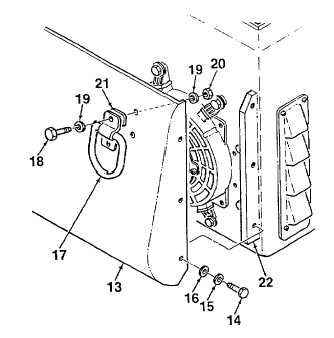
Remove nosepiece assembly (13) from brackets
(22) by removing six screws (14), lockwashers (15),
and washers (16).
9.
Remove two tie down rings (17) from nosepiece
assembly (13) by removing screws (18), washers
(19), and locknuts (20). Remove gaskets (21).
B. INSPECTION.
Inspect hoist ring and tie down rings for cracks or
other damage.
C. REPAIR.
1.
Repair
painted
and
stenciled
surfaces
in
accordance with Para. 4-11.
2.
Repair of parts, other than painting, is limited to
removal and replacement of damaged components.
Figure 4-6. Tie Down and Hoist Rings
(Sheet 2 of 2)
D. INSTALLATION.
1.
Install two tie down rings (17, Figure 4-6) and gaskets (21) onto nosepiece assembly (13) using screws (18),
washers (19), and locknuts (20).
2.
Apply a thin bead of silicon adhesive to lip at top of nosepiece (13) that mates with enclosure. Apply adhesive to top
3 inches of lip on each side of nosepiece as well.
3.
Mate nosepiece assembly (13) to brackets (22) and secure using six screws (14), lockwashers (15), and washers
(16).
4.
Install right hand tie down ring (7) and gaskets (11) onto rear panel of enclosure (8) using screws (12) and locknuts
(10).
5.
Install left hand tie down ring (7), gasket (11), and control panel mounting block using screws (9) and locknuts (10).
6.
Install hoist ring (1), blocks (2), and rubber strip (6) onto cover assembly cross member using screws (3), washers
(4), and locknuts (5).
7.
Install local control panel (Para. 4-20). Install fuel module (Para. 4-32). Install APU cover assembly (Para. 4-12).
8.
Connect NATO plug to receptacle and secure using strap.
4-49