TM 9-6115-664-13&P
4-20. LOCAL CONTROL PANEL ASSEMBLY MAINTENANCE
C.
INSPECTION.
1.
Inspect electrical connector on rear of control panel for corrosion and cleanliness. Ensure connector is securely
fastened.
2.
Inspect electrical wiring harness for cuts, abrasions, bare wires, and evidence of short circuits. Inspect wire
insulation for damage. Ensure electrical connectors are securely attached.
3.
Check control panel switches for proper operation. Inspect panel markings for legibility.
4.
Inspect control panel gasket for cuts, tears, permanent set, deterioration, or other damage. Ensure gasket is
securely attached.
D.
REPAIR.
1.
Remove corrosion from electrical connectors.
2.
Remove and replace damaged gasket. Cut new gasket to length and peel off tape to expose adhesive.
3.
Repair of control panel assembly consists of removal and replacement of damaged components. Refer to
appropriate paragraphs for detailed procedures.
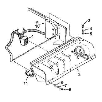
E. INSTALLATION.
1.
Mate control panel assembly (2, Figure 4-10) to
APU enclosure. Ensure sealing gasket is properly
seated. Apply silicon adhesive to threads of three
screws (6) and secure control panel assembly
using screws, washers (7), and lock-washers (8).
2.
Apply silicon adhesive to threads of two screws (3).
Secure control panel assembly (2) to mounting
blocks
(9)
using
screws,
washers
(4),
and
lockwashers (5).
3.
Connect electrical connector (1) to rear of control
panel assembly (2). Secure wiring harness to back
of control panel using plastic clamp (11).
4.
Close top rear cover and lock by turning latches.
5.
Connect NATO plug into receptacle and secure
using strap
Figure 4-10. Local Control Panel. (Sheet 2 of 2)
4-54