TM 9-6115-664-13&P
4-14. VALVE ACCESS DOOR MAINTENANCE
5.
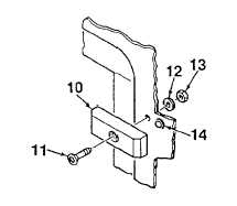
Remove
two
door
latches
(10)
from
APU
enclosure by removing screws (11), washers (12),
and locknuts (13).Remove detent plungers (14) by
unscrewing from enclosure.
B.
INSPECTION.
1.
Inspect door for dents, cracks, warping, or other
damage. Inspect painted surfaces for chips,
scratches, bare metal, roughness, or corrosion.
2.
Inspect door latches for proper operation. Latches
should operate smoothly, free of binding.
Figure 4-4. Access Door
(Sheet 2 of 2)
3.
Inspect exhaust louver for obstructions, clogging, or damage. Check louver fins for damage.
4.
Inspect engine exhaust bellows for damage. Make sure there are no holes or tears on bellow material. Ensure
secure connection to engine exhaust manifold.
C.
REPAIR.
1.
Remove and replace damaged door gasket as required. Cut bulk gasket to length and secure by peeling off tape to
expose adhesive.
2.
Repair painted and stenciled surfaces in accordance with Para. 4-11.
3.
Repair of parts, other than painting, is limited to removal and replacement of damaged components.
D.
INSTALLATION.
1.
Install two latches (10, Figure 4-4) onto APU enclosure using screws (11), washers (12), and locknuts (13). Screw
in detent plungers (14).
2.
Mate door (2) to enclosure. Secure hinge (9) to enclosure surface using five screws (6), ten washers (7), and five
locknuts (8).
3.
Close door (2) and lock by turning door latches (10).
4.
Mate engine exhaust bellows (1) to rear of door (2). Secure using screw (3), lockwasher (4), and washer (5).
5.
Close front cover and secure by locking latches.
6.
Connect NATO plug to receptacle and secure using strap.
4-45


