
TB 9-6115-645-13
8.
Re-attach the baffle (5), Figure5-2, with the heater mounted to it.
9.
Apply two good beads of RTV around exhaust port of heater (3), Figure 5-1, and point the exhaust elbow (9) in the
desired direction to route the exhaust hose (5) to come out the top of the inner ceiling of the generator as shown in
10.
Drain coolant system in accordance with TM 9-6115-645-24.
NOTE
Seal all pipe threads with sealing compound contained in kit.
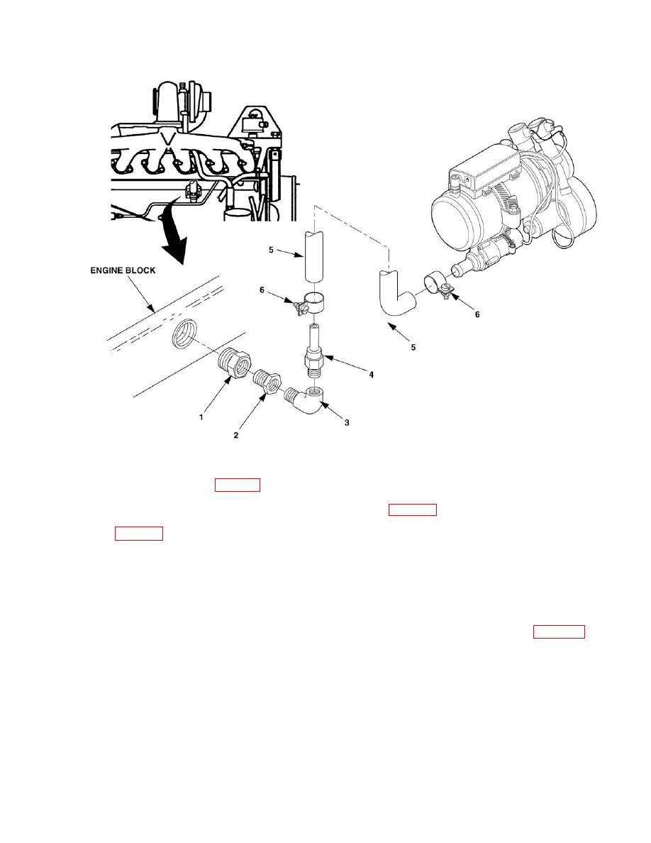
11.
Remove plug from rear of engine head (refer to engine TM 9-6115-256-24) and install adapter (1), Figure 5-4,
bushing (2), elbow (3), and adapter (4).
12.
Install coolant hose (5) to elbow (3) and adapter (4) and secure with clamp (6). Install the other end of the coolant
hose (5) to heater coolant intake using clamp (6).
13.
Install the other end of the coolant hose (5) to heater coolant intake using clamp (6).
