TB 9-6115-645-13
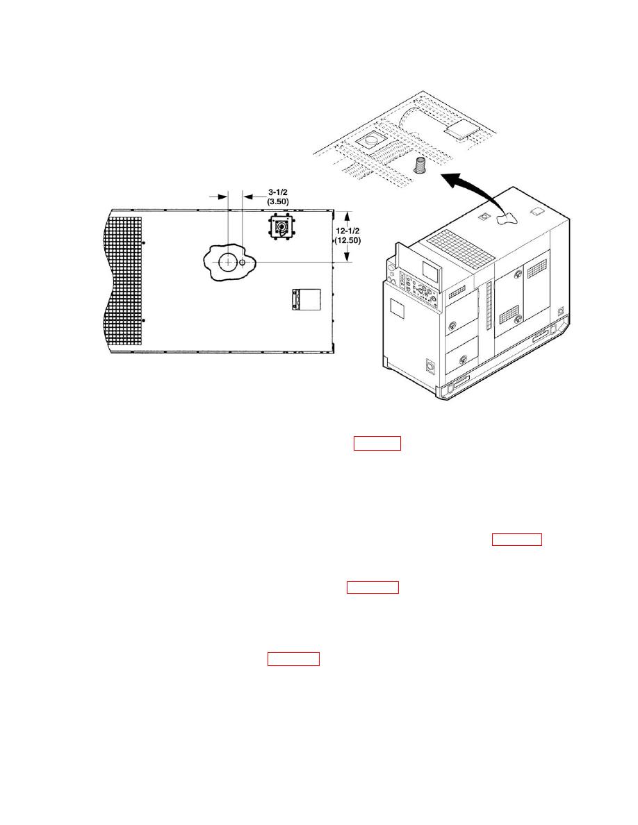
Figure 5-8. Exhaust Hose Assembly
25.
Provide a 1 7/16" diameter hole in duct floor as shown in Figure 5-8.
26.
Install exhaust hose through hole. Use sealant contained in kit on hose and around hole to prevent movement.
27.
Install exhaust clamp on existing screw hole on top of exhaust manifold using 3/8" thread screw.
28.
Open right front upper panel door.
29.
Remove wire 172D from P6-18 and tie back in harness with straps provided in kit. Refer to Figure 5-3.
30.
Remove pins from P6-17 and 19.
31.
Install wiring harness in accordance with wiring diagram Figure 5-3. Secure harness with straps contained in kit.
NOTE
Install fuse, (25 AMP, 32V) if not already installed.
32.
Connect fuse holder wire, part of (2), Figure 5-3, to (+) terminal of the slave receptacle. Install fuse F1 into
fuse holder (1).


