
TB 9-6115-645-13
36.
Install rivets (3) contained in kit. Rivet heads shall be on the outside of the unit.
37.
Remove control box top. Refer to TM 9-6115-645-24 and remove ether switch and wire 172A from TB5-9
and wire 190D from TB6-8. Tie back switch and wires in harness with straps contained in kit.
38.
Locate heater switch label (7), Figure 5-9, with existing hole for switch and drill hole in control panel for the light
indicator.
39.
Install heater switch label (7), toggle switch (4) and indicator light (5).
40.
Remove wire 172C from J6-18 using pin removal tool and tie back in harness with straps contained in kit.
41.
Remove pins from J-17 and 19 using pin removal tool.
42.
Install electrical leads in accordance with wiring diagram Figure 5-3. Secure leads with straps contained in kit.
Engine Air
Breather
8
1
2
5
TO TB-7
3
PIN 8
8
6
TO TB-7
4
PIN 9
7
TO TB-7
PIN 9
TO TB-7
PIN 10
WARNING
The coolant in the system shall contain the proper mixture of water and
antifreeze to prevent coolant from freezing or slushing. Failure could
cause engine damage and/or personal injury.
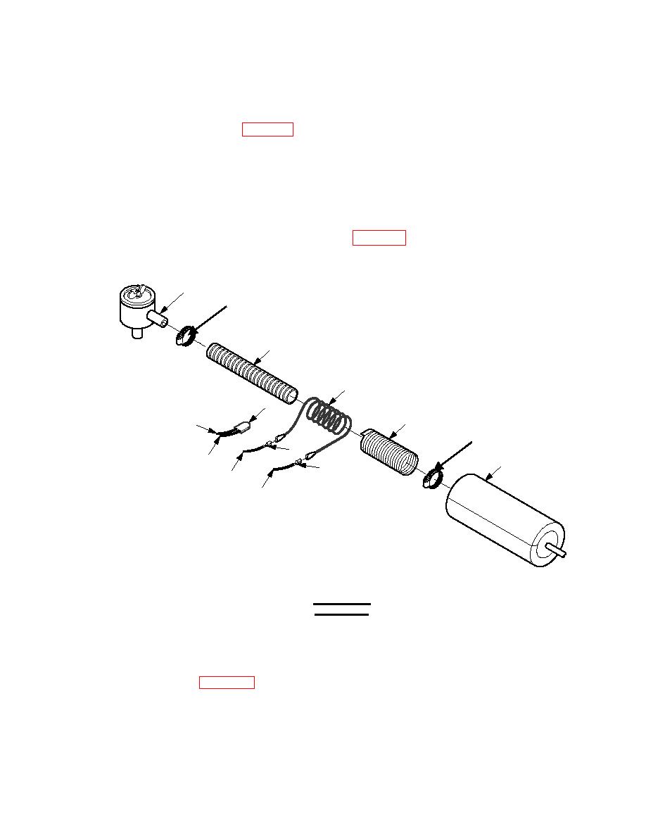
43.
Remove clamps (8), Figure 5-10, and discard hose from crankcase breather air intake tube in accordance with
TM 9-6115-645-24. Wrap rope heater (2) assembly spirally on new air breather hose (1) provided in kit
approximately five (5) revolutions, leaving approximately six (6) inches of rope heater (2) on each end of hose.
Wrap rope heater (2) and air breather hose (1) with foil tape (3) provided in kit. Install pipe insulation (4) over air
breather hose (1), rope heater (2), and foil tape (3), leaving rope heater wires exposed for electrical connection.
Install assembled air breather hose (1) between crankcase breather and air intake hose. Secure air breather hose (1)
with clamps (8) removed from above.
