TM 9-6150-228-13&P
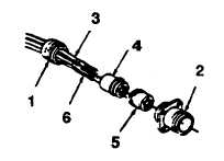
Figure 5-10. MS Connector.
NOTE
Splicing cables is not authorized. Cables that are damaged may be repaired by cutting
off damaged section and reattaching connector.
c. Assembly Connector.
(1) Install wires (3) with sockets (6) attached into rear support group (4).
NOTE
Sockets lock in place in support group (4).
(2) Position forward support group (5) over sockets (6).
NOTE
• Make certain position markings on forward and rear support groups match.
• Forward support group (5) and connector (2) are keyed to fit together.
(3) Install rear support group (4), forward support group (5) and wires (3) into connector (2).
NOTE
Nut (1) has left-hand thread.
(4) Install nut (1) on connector (2).
5-21

