TM 9-6115-647-14&P
4880-065
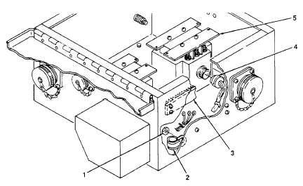
Figure 4-14. P9 Wiring Harness Replacement.
f.
Control Relay/Diodes Wiring Harness Replacement. (See figures 4-9 and 4-15).
(1) Removal.
(a) Release cover latch and open PDU cover.
(b) Remove two screws (1, figure 4-15) and two washers (2) and unplug relay (3) from socket (4).
(c) Unsolder one harness wire from top of each of four diodes (5).
(d) Remove one wire with terminal (6) from bottom of each of four diodes (5).
(e) Detach opposite ends of harness wires from terminal board TB1 (7). (See figure 4-9 for termination
of each wire).
(f)
Remove all tiedown straps (8) binding control relay/diodes wiring harness to other PDU wire
bundle.
(g) Remove two nuts (9) and unscrew two threaded mounting studs (10) from socket (4).
(h) Grasping socket (4), pull remaining five harness wires up through cutout in bracket (11).
NOTE
Screws (1), washers (2), mounting studs (10), nuts (9) and socket (4) are part of
control relay/diodes wiring harness and must be kept with rest of harness.
(2) Installation.
(a) Push five harness wires soldered to socket (4) through socket cutout in bracket (11).
4-39