TM 9-6115-647-14&P
(c)
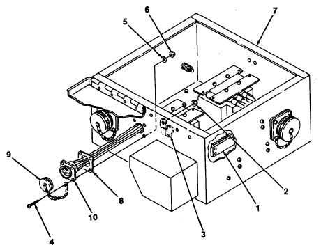
Seat flange of connector J6 (10) against housing (7) and fasten with four screws (4),
four flat washers (5) and four nuts (6). Make sure tab of connector cover chain (9) is
mounted to flange with lower right corner hardware.
(d)
Install connector cover (9) on connector J6 (10).
(e)
Using figure 4-9 for wire routing information, connect wires to terminal board TB1 (1).
(f)
Route wires through clamps (3) and install nuts (2). Bind J6 harness to J1 harness with
tiedown straps.
(g)
Close and secure PDU cover.
Figure 4-11. J6 Wiring Harness Replacement.
c.
J10 Wiring Harness Replacement. (See figure 4-9 and 4-12.).
(1)
Removal.
(a)
Release cover latch and open PDU cover.
(b)
Detach J10 wiring harness wires from terminal board TB1 (1, figure 4-12) and ground
stud E1 (2).
4-35