TM 9-6115-647-14&P
Figure 4-12. J10 Wiring Harness Replacement.
d.
P8 Wiring Harness Replacement. (See figures 4-9 and 4-13).
(1) Removal.
(a) Release cover latch and open PDU cover.
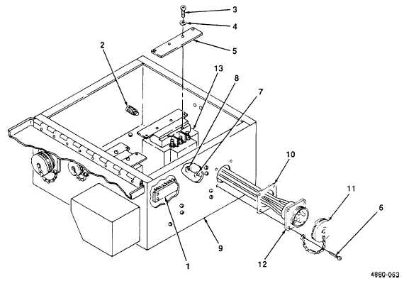
(b) Remove nut (1, figure 4-13) and open clamp (2). Remove four P8 harness wires.
(c) Detach P8 wiring harness wires from terminal board TB1 (3).
(d) Unplug connector P8 (4) from connector J8 on contactor K1 (5).
(2) Installation.
(a) Plug connector P8 (4) into connector J8 on contactor K1 (5).
(b) Using figure 4-9 for wire routing information, connect harness wires to terminal board TB1 (3).
(c) Route wires through clamp (2) and install nut (1).
(d) Close and secure PDU cover.
4-37