TM 9-6150-226-13
5-10 CABLE CONNECTOR. (cont)
(1)
(2)
(3)
(4)
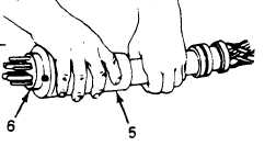
(5)
(6)
(7)
(8)
(9)
(10)
(11)
(12)
NOTE
Refer to paragraph 5-9b to determine correct pin-
to-key position connector.
The following is an alternate procedure for the
100-amp, 8-pin; 40/60-amp, 5-pin; and 60-amp, 4-
pin cable connectors.
This procedure is a method
for inserting the pins collectively into the
support group.
Start the
Start the
Slide support
Start the
A-pin into support group (6).
N-pin into support group (6).
group (6) halfway over the A- and N-pins.
B-pin into support group (6).
Start the C-pin into support group (6).
Slide support group (6) as far as possible over all the pins.
Rock support group (6) toward the A-pin until it locks into
position.
Rock support group (6) toward the N-pin until it locks into
position.
Grasp the C-pin wire and push the wire
while rocking the support group toward
into position.
Grasp the B-pin wire and push the wire
while rocking the support group toward
into position.
toward support group (6)
the C-pin until it locks
toward support group (6)
the B-pin until it locks
Select a G-pin wire nearest to its support group (6) hole. Use
long-nosed pliers to grasp the pin and insert the pin into its
hole and lock in position.
Insert remaining G-pins into support group
(6) as described above.
b.
Slide connector body (5) down cable and posi
tion support group (6) and connector body
together.
5-23