TM 9-6150-226-13
5-10 CABLE CONNECTOR. (cont)
g.
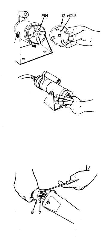
Refer to Tables 5-2 and 5-3
and select proper crimping
die (12) and install onto
crimper so pin and hole aline.
Install retaining ring.
h.
Slide pins onto cable wire
and crimp in place.
4.
ASSEMBLE CONNECTOR.
WARNING
High voltage is present
in this system.
DISE
and PDISE supports equip-
ment using 120/208 V ac.
Do not rely on the color
of the wire insulation for
phase color-coding. The
insulation on the wires
inside the cable jacket
may vary, depending on the
supplier.
Wires will be
color coded to designate
the phases. Perform a
continuity test to verify
correct phase designation
in accordance with
identified color.
Refer to paragraph 5-9a
to determine correct
pin letter and wire color
code.
Use lubricant (item 3,
App E) to aid installation
of pins (7) into support
group (6).
a.
Use proper insert tools (Tables
5-2 and 5-3) and insert pins (7)
into support group (6).
5-22