TM 9-6150-226-13
5-10 CABLE CONNECTOR.
(cont)
3.
INSTALL CONNECTOR PARTS.
a.
b.
c.
d.
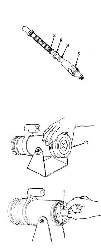
Install wire mesh (2), glands
(9) and (8), and connector
body (5).
Cut and remove proper length
of insulation from outer cable
jacket and wires (refer to
para 5-9d).
Use a multimeter (item 3,
App B) and perform a continuity
test (Table 4-8) to determine
correct pin-to-wire
installation.
Tag wires with colored tape
(items 10 thru 15, App E) in
accordance with paragraph 5-9a.
NOTE
The long pin attaches to
the neutral wire of the
male connector.
e.
Remove pneumatic crimper die
retaining ring (10) and crimper
die.
f.
Refer to Tables 5-2 and 5-3 and
select the proper pin/socket
locator.
Place locator (11)
into crimper so notches in
crimper and locator aline.
5-21