TM 9-6150-226-13
4-17 CIRCUIT BREAKER ASSEMBLY AND BUS BAR. (cont)
d.
e.
f.
g.
h.
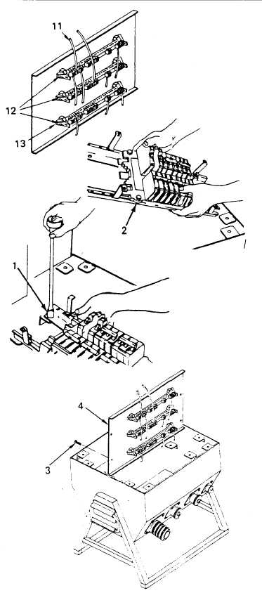
Install neutral (16), and
ground (12) bus bars and secure
with screws (17), washers (19)
nuts (18).
Install screw (20), washer (19),
and nut (18) securing ground strap.
Refer to tags and connect
wiring (14) to bus bars.
Secure phase bus bars (12) with
screws (13).
Refer to tags and connect
wiring (11) to bus bars (12).
Remove tags and torque terminal
lugs in accordance with Table G-1.
4. INSTALL CIRCUIT BREAKER ASSEMBLY.
a.
b.
c.
d.
e.
f.
NOTE
If you have PDISE equip-
ment, follow instructions
in paragraph 4c, d and e.
Install circuit breaker
assembly (2) and secure with
screw (1).
Solder dip or solder gun wire ends,
not to exceed .025 inches, using Kester
Solder MIL Spec No. QQ-S-571
(Sn 60 Pb 40)
Refer to tags and connect
receptacle/plug wiring to
circuit breakers. Remove
tags and torque in accordance
with Table G-1.
NOTE
Don’t secure circuit breaker
assembly when performing
continuity test.
Connect wiring J2, A, B and C
to bus bars.
Install circuit breaker
assembly (4) and secure with
screws (3).
Refer to tags and connect
wiring to circuit breakers.
Change 1
4-51


