TM 9-6150-226-13
4-19 DUPLEX RECEPTACLE AND CABLE.
(cont)
4.
5.
6.
7.
REPLACE DEFECTIVE PARTS.
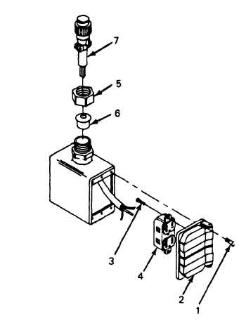
INSTALL CABLE ASSEMBLY.
a.
Install cable assembly (7)
in receptacle box.
b.
Install gland (6) in place
and secure with gland
nut (5).
INSTALL DUPLEX RECEPTACLE.
a.
Remove tags and connect
wires.
b.
Install duplex receptacle (4)
on door assembly (2) and
secure with screws (3).
INSTALL DOOR ASSEMBLY.
Place door assembly
secure with screws (1)
(2) on box and
TEST
WARNING
High voltage is present in this system. DISE and
PDISE supports equipment using 120/208 V ac. Do
not attempt continuity checks with the power on.
Death or serious injury may result.
PERFORM CONTINUITY TEST.
Refer to Table 4-5 and perform continuity test on the duplex receptacle.
4-55