ARMY TM 9-6115-671-14
AIR FORCE TO 35C2-3-446-32
MARINE CORPS TM 09249A/09246A-14
5-19
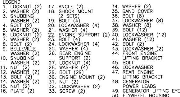
(11) Secure generator to skid base with snubbing washers (10), Belleville washers (9), bolts (8),
washers (7), and locknuts (6). Torque bolts to 210 ft-lb (284.9 Nm).
(12) Secure engine supports (22) to skid base with washers (5), bolts (4), snubbing washers (3),
washers (2), and locknuts (1). Torque locknuts to 75 ft-lb (101.7 Nm).
(13) Adjust nuts (11 and 15) to obtain 0.5 in. minimum clearance between ends of bolts (13) and skid
base. Torque bolts to 150 ft-lb (203 Nm).
(14) Install right and left side generator housing panels as complete assemblies.
(15) Connect main output terminal board ground strap to skid.
(16) Pull main alternator output wires, T1 through T12, and rotor exciter wires, F1 and F2 through
hole in bottom of output box.
(17) Install rear generator housing section (paragraph 4.7.5).
(18) Connect rotor exciter wires, F1 and F2 to TB8.
(19) Install main alternator output wires, T1 through T12, to current Transformer (CT1) and droop
current transformer (CT5).
(20) Connect main alternator output wires, T1 through T12, to voltage reconnection switch.
(21) Connect fuel vent line at fuel filler neck to t-connection above starter.
(22) Connect fuel line to engine mechanical fuel pump.
(23) Connect wires to starter, including the ground wires. Remove tags.
(24) Connect wiring harness to ether injection solenoid and relay. Remove tag.


