TM 9-6115-664-13&P
5-13. SPEED CONTROL AND PRIMER ASSEMBLY MAINTENANCE
2.
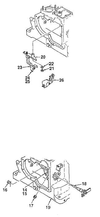
Screw bushing (25) into speed control lever (15)
until bushing is flush with rear side of lever. Push
bolt (24) into bushing.
3.
Insert the leg of return spring (16) up into hole in
speed control lever (15). Bend leg 15 towards
middle of lever to hold in place.
4.
Place primer assembly control lever (11) over
speed control lever (15). Hold levers in place in
engine block (19).
5.
Hold acceleration lever (29) in the stop position
and insert speed control eccentric shaft (18)
through bushing in side of engine block (19).
6.
Push levers (11, 15) onto eccentric shaft (18).
Return spring (16) shall fit into eccentric shaft slot
without resistance.
7.
Turn acceleration lever (29) to full load position.
8.
Rotate speed control eccentric shaft (18) while
pulling it slightly out of the engine block bushing.
Press speed control control lever (15) in the
direction of the crankcase wall until the pin on
lever (15) engages in the fork pin of lever (24).
9.
Push eccentric shaft (18) back into bushing and
secure using retaining clip (17).
10.
Turn acceleration lever (29) to the full load
position.
Figure 5-7. Speed Control and Primer
(Sheet 4 of 5)
5-40


