TM 9-6115-664-13&P
5-13. SPEED CONTROL AND PRIMER ASSEMBLY MAINTENANCE
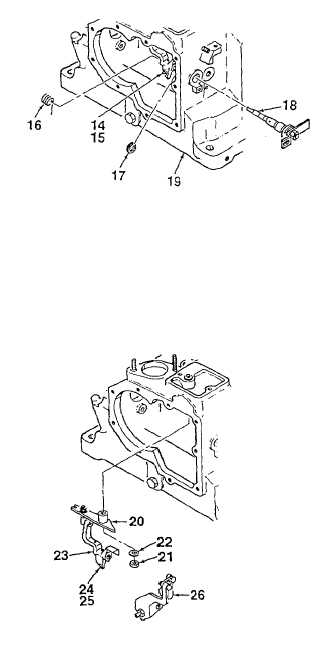
8.
Using governor adjustment tool, loosen bushing
(14, located in speed control lever (15)) by 3
revolutions.
9.
Remove retaining clip (17) from speed control
eccentric shaft (18). Rotate shaft in the stop
direction until return spring (16) is unhooked.
Remove shaft as an assembly from engine block
(19). Place on a suitable work surface for further
maintenance.
10.
Remove lever (20) and attaching parts on if
damaged by removing nut (21) and washer (22).
11.
Remove bolt (24) and bushing (25) from speed
control lever (15). Remove primer assembly (26).
Figure 5-7. Speed Control and Primer
(Sheet 2 of 5)
5-38