TM 9-6115-664-13&P
5-13. SPEED CONTROL AND PRIMER ASSEMBLY MAINTENANCE
This task covers removal, inspection, and installation
INITIAL SETUP
Tools:
Equipment Condition:
Shop Equipment, Automotive Maintenance
Camshaft Assembly Removed (Para. 5-12)
and Repair (Item 4, App. B)
Oil Filler Removed (Para. 4-53)
Governor Adjustment Tool (Item 5, App. B)
Parts/Materials:
Cleaning Solvent, PD-680 (Item 9, App. E)
A.
REMOVAL
1.
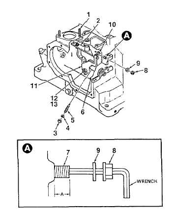
Unscrew right hand injection pump stud (1, Figure
5-7) until transverse lever (2) is released.
2.
Remove nut (3), lockwasher (4), and threaded pin
(5) from eccentric shaft (6).
3.
Hold threaded pin (7) in place using an alien
wrench. Remove collar nut (8) and washer (9)
from threaded pin.
4.
Measure and record Dimension A.
5.
Screw threaded pin (7) into the engine block until
flange bolt (10) on primer assembly control lever
(11) disengages from the segment.
6.
Screw threaded pin (7) out until it protrudes
approximately 5 mm (3/16 in.) from surface of
engine block.
7.
Unhook small spring from primer assembly control
lever (11). Remove threaded pin (12) and nut
(13).
Figure 5-7. Speed Control and Primer
(Sheet 1 of 5)
5-37