TM 9-6115-664-13&P
4-26. SWITCH ASSEMBLY MAINTENANCE (REMOTE CONTROL PANEL)
This task covers removal, inspection, testing, and installation
INITIAL SETUP
Tools:
Equipment Condition:
Shop Equipment, Automotive Maint enance
Remote Cable Disconnected From
and Repair (Item 1, App. B)
Local Control Panel Assembly
A. REMOVAL.
CAUTION
Use care when separating remote
control front panel from housing to
prevent damage to electrical wiring.
NOTE
Discard and replace all lockwashers
and locknuts when removed.
1.
Remove front panel (1, Figure 4-16) from remote
housing
(2)
by
removing
six
screws
(3),
lockwashers (4), and washers (5).
2.
Disconnect remote cable electrical connector (6)
from circuit board assembly. Tag and disconnect
electrical wires from switches as required for
maintenance.
3.
Remove START / PRIME RUN / OFF switch (7)
from front panel (1) by removing attaching nut (8)
and washer (9).
4.
Remove OIL / AIR PREHEAT switch (10) from
front panel (1) by removing attaching nut (11) and
washer (12).
5.
Remove BATTLE SHORT switch (13) from front
panel (1) by removing attaching nut (14). Remove
switch guard (15).
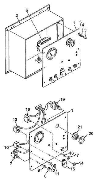
Figure 4-16. Switch Assembly
4-66