ARMY TM 9-6115-644-24
AIR FORCE TO 35C2-3-446-12
MARINE CORPS TM 09249A/09246A-24/2
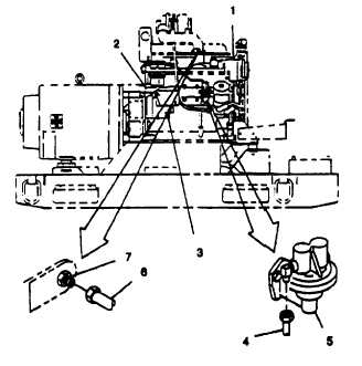
ao. Open right side engine access doors, tag and dinned electrical leads from battery charging alternator (1,
FIGURE 3-13). starter solenoid (2) and starter motor (3).
ap.
Disconnect fuel line (4) at fuel pump (5). Cap openings.
aq.
Disconnect tube (6) from ether start spray nozzle (7) at intake manifold.
ar.
Remove nut (1, FIGURE 3-14) lockwashers (2), and bolt (3) securing ground strap (4) to skid base.
as.
Remove bolts (5), washers (7), and lockwashers (6) securing load output terminal board assembly (8) to sup-
ports (9) and (10). Pull load output terminal board assembly out through access door.
at.
Remove assembled nuts (11), bolts (12), and support (10) from right side panel
au.
Loosen nuts (23 and 27, FIGURE 3-1), turn bolts (25) to contact skid base and tighten nuts (23) and (27).
av.
Remove nuts (30,) lockwashers (31), screws (32,) washers (33), and screen/cover (34) from generator case.
FIGURE 3-13. Right Side Engine
3-21