ARMY TM 9-6115-644-24
AIR FORCE TO 35C2-3-446-12
MARINE CORPS TM 09249A/09246A-24/2
f.
2-46-3.1.
a.
b.
c.
d.
e.
f.
g.
h.
i.
Remove GROUND FAULT CIRCUIT INTERRUPTER (23) from malfunction indicator panel (27).
In-Line Fuse Installation.
NOTE
The following procedures applies to generator sets under contract number DAAK01-
88-D-D082.
Shut down generator set.
Open left side engine access door and disconnect negative battery cable.
Remove malfunction indicator panel screws (24, FIGURE 2-14), washers (25), and nuts (26). Lay
malfunction indicator panel to the side.
Cut black wire on load side of GROUND FAULT CIRCUIT INTERRUPTER (23).
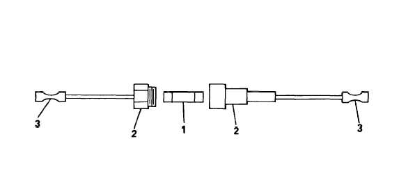
Strip wires on in-line fuse holder (2, FIGURE 2-13.1) and install butt splices (3) at each end.
Connect ends of black wire to in-line fuse holder butt splices (3).
Install fuse (1) in fuse holder (2).
Secure excess wire to wiring harness using tie wrap.
Install malfunction indicator panel (27, FIGURE 2-14), screws (24), washers (25), and nuts (26).
Reconnect negative battery cable and close battery access door.
NOTE
When replacing GROUND FAULT CIRCUIT INTERRUPTER, use new GROUND
FAULT CIRCUIT INTERRUPTER with integral circuit breaker. Refer to TM 9-6115-
644-24P for new part number.
FIGURE 2-13.1. In-Line Fuse Installation
Change 1
2-82.1/(2-82.2. blank)