TM 5-6115-629-14&P
4-25.
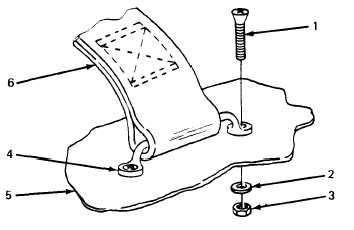
Holddown Strap Replacement. (See figure 4-12.) Three holddown straps are provided on the
roadside fender of each power unit. These straps are used to secure the power cables when the power
plant is in transit. Replacement procedure is typical.
a. Removal.
(1) Remove two screws (1, figure 4-12), two washers (2), and two nuts (3) securing foot-
mans loop (4) to trailer (5).
(2) Slide holddown strap (6) off footmans loop (4).
b. Installation.
(1) Slide holddown strap (6) onto footmans loop (4).
(2)
Position footmans loop (4) on trailer body (5) and secure with two screws (1), two
washers (2), and two nuts (3).
Figure 4-12. Holddown Strap Replacement.
SECTION IX. MAINTENANCE OF ELECTRICAL SYSTEM
4-26.
General. This section of the manual contains unit level maintenance procedures for electrical
components that are unique to the AN/MJQ-12A power plant. Specifically, this includes the switch box
and the power cables.
4-27 Cable Testing. A continuity test is used to detect opens or shorts in the power plant power
cables. The two cables differ from each other only in length. The following test procedure is typical for
both.
a. Set multimeter controls to prepare unit for continuity testing.
NOTE
The contacts in the connector end of cable are labeled A, B, C, N, and G1
thru G4. The individual colored wires at the other end of cable are labeled L0,
L1, L2, L3, and GEN GND.
b. Touch one probe to contact A in connector and touch remaining probe to black wire labeled
L1. Multimeter must indicate continuity. If it does not, cable is open.
4-27