TM 11-6125-252-15
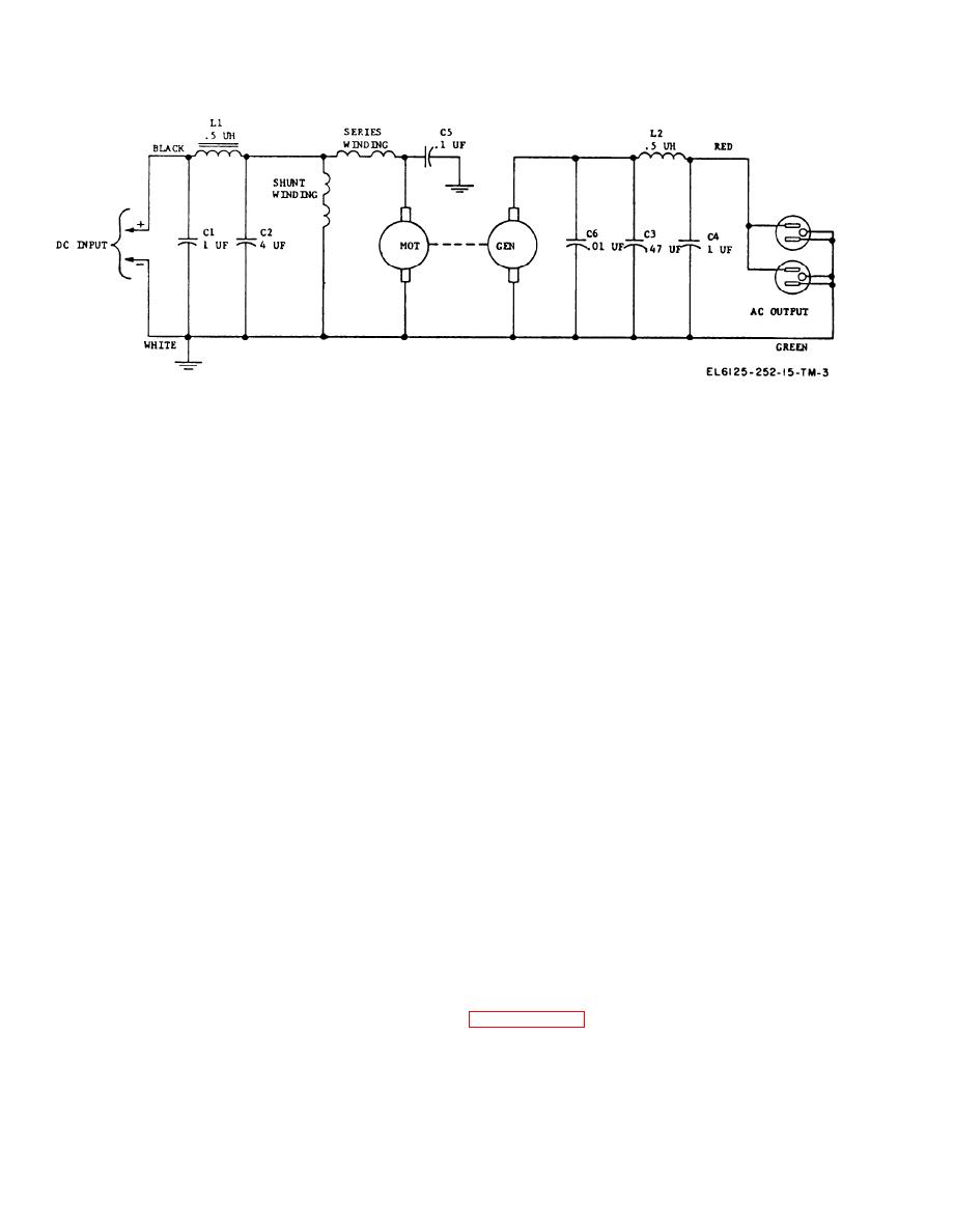
Figure 5-2. Motor generator, schematic diagram.
circuited and must be replaced. The best test for
tests), disconnect the dc power supply. Multime-
a capacitor is to substitute a good capacitor for
ter TS352B/U may be used for making con-
the one suspected of being faulty. To be safe,
tinuity tests and checking dc voltage and current.
replace any capacitor suspected of causing
(1) Armature Test.
trouble.
(a) Test for ground. First lift the brushes
(3) Field test.
from both the commutator and sliprings and
(a) Lift the brushes from the armature
block them in the raised position. With Mul-
commutator and block them in the raised posi-
timeter TS-352B/U, test between the armature
tion. With Multimeter TS-352B/U, test the shunt
shaft and each slipring. Test between the arma-
field coil circuit for continuity. If circuit is com-
ture shaft and each segment of the commutator.
plete, check resistance of the total field circuit.
A closed circuit reading indicates that the part
The resistance should be from 17 to 19 ohms at
under test is shorted to ground. Check for worn
20 C. If circuit is open or resistance is incorrect,
or dirty insulation or foreign metallic materials.
field shell assembly must be replaced unless broken
(b) Test for open circuit. Place one of the
wire is located.
test prods of the multimeter on one of the seg-
(b) Check series field for continuity be-
ments of the commutator. Place the other test
tween A+ terminal, located on the dc input ter-
prod on the adjoining segment. Keep the first
minal strip in the filter box, and positive brush
prod in contact with the one segment and move
holder.
the second prod from segment to segment, com-
pletely around the commutator, until a check of
5-5. Troubleshooting Charts for Motor
all commutator segments has been made. No read-
ing indicates an open circuit. If an open circuit
is indicated, inspect the soldered connection on
The troubleshooting charts that follow list vari-
the end of the segment. To test the ac circuit,
ous troubles and trouble symptoms that may be
place one test prod on each of the sliprings. No
readily detected. When the type of trouble has
reading indicates that the circuit is open.
been determined, check the various points listed
under possible causes and then correct the diffi-
(2) Capacitor tests. Before testing a capaci-
culty in accordance with instructions listed under
tor, disconnect one end. Make a continuity test
remedy. Where disassembly is required, refer to
between the two terminals of the capacitor. If
continuity is indicated, the capacitor is short
5-2


