TM 9-6150-228-13&P
b. External Cable Assembly.
(1)
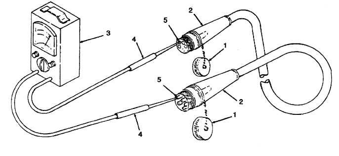
Unscrew and remove covers (1, Figure 4-15) from cable connectors (2).
(2)
Preset multimeter (3) to perform continuity testing.
(3)
Refer to power cable wiring diagram (Figure 4-1) and Table 4-4. Touch probes (4) of multimeter to each pair of
contacts (5) as shown in Table 4-4. Continuity should be as specified in Table 4-4.
(4)
Install covers (1) on cable connectors (2).
Figure 4-15. External Cable Assembly.
4-41