
TM 9-6115-730-24
0014
OUTPUT VOLTAGE SETTING - Continued
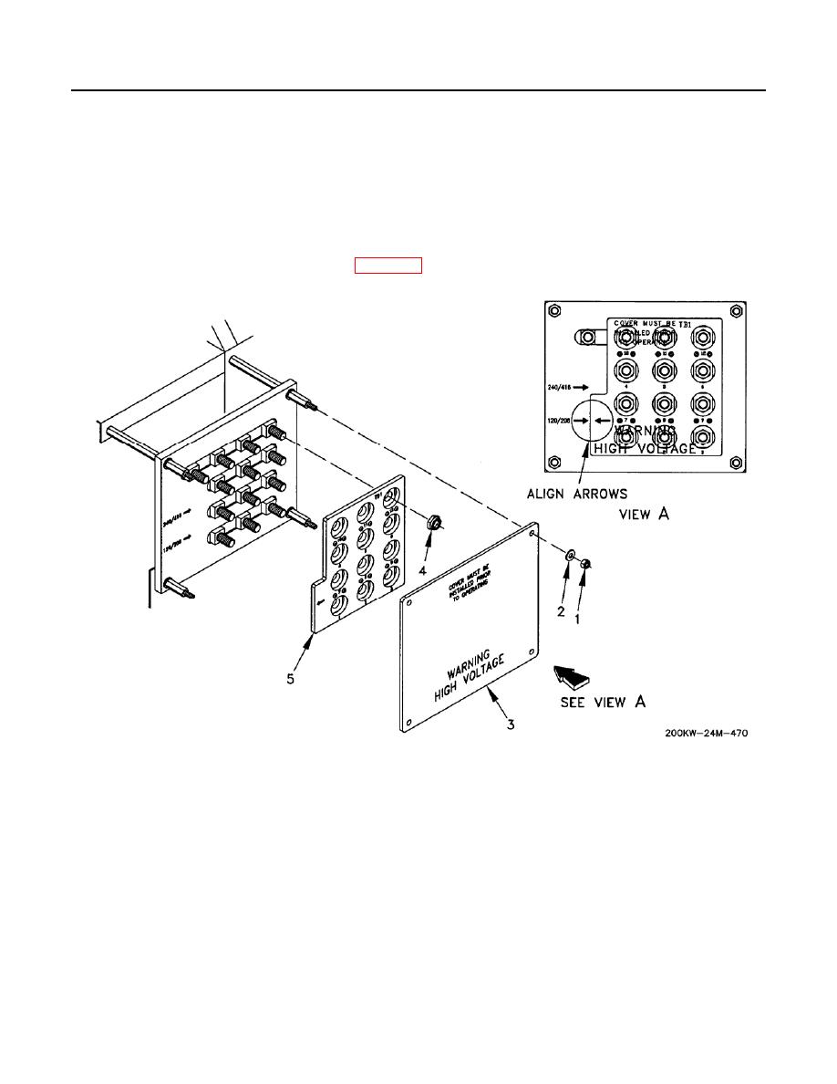
6. Install reconnection board (Figure 1, Item 5) and secure with 12 nuts (Figure 1, Item 4).
7. Install clear protective panel (Figure 1, Item 3) and secure with four washers (Figure 1, Item 2) and nuts
(Figure 1, Item 1).
8. Close right rear doors.
9. Reprogram DVR and GSC, as required per WP 0083.
Figure 1. Reconnection Terminal Board Voltage Setting.
END OF WORK PACKAGE
