ARMY TM 9-6115-672-14
AIR FORCE TO 35C2-3-444-32
MARINE CORPS TM 09244A/09245A-14
4-124
(9)
Install DCS control box top panel, paragraph 4.7.2.
(10) Connect negative battery cable to battery, and close BATTERY ACCESS door.
4.8.29 Diode CR1-CR10
a. Inspection.
(1)
Shut down generator set, paragraph 2.11.2.
(2)
Remove DCS control box top panel, paragraph 4.7.2.
(3)
Inspect diode (9, Figure 4-16) for cracks, breaks, corrosion, bent terminals, and other damage.
(4)
Install DCS control box top panel, paragraph 4.7.2.
b. Testing.
(1)
Shut down generator set, paragraph 2.11.2.
(2)
Open BATTERY ACCESS door (Figure 1-2), and disconnect negative battery cable.
(3)
Remove DCS control box top panel, paragraph 4.7.2.
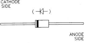
FIGURE 4-17. DIODE IDENTIFICATION
(4)
Tag and remove diode from circuit. Refer to Schematic FO-1.
(5)
Connect positive lead of multimeter to cathode side and negative lead to anode side of diode (9,
Figure 4-16). Refer to Figure 4-17. Multimeter should indicate open loop for diode.
(6)
Reverse multimeter leads so positive lead is connected to anode and negative lead is connected to
cathode side of diode. Multimeter should indicate continuity for diode.
(7)
If any indications are other than above, replace diode.
(8)
Install DCS control box top panel, paragraph 4.7.2.