ARMY TM 9-6115-671-14
AIR FORCE TO 35C2-3-446-32
MARINE CORPS TM 09249A/09246A-14
5-39
b. Testing.
(1)
Remove droop current transformer, step 5.8.5.a above.
(2)
Set multimeter for ohms, and check for continuity between secondary leads 1 and 2. If
continuity is present, continue with test. If continuity is not present, droop current transformer is
defective and must be replaced.
(3)
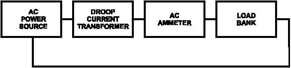
Set up a test circuit using 10 gauge wire as shown in Figure 5-6. Make 10 passes with wire
through window of droop current transformer.
(4)
Turn on power source and load bank. Adjust load bank until 20.8 amps is indicated on AC
ammeter.
(5)
Set multimeter for AC amperes, and connect to secondary leads 1 and 2. Multimeter indication
must be 0.9 to 1.1 amps.
(6)
Replace droop current transformer if multimeter indication in any phase is other than stated in
step (5).
FIGURE 5-6. TESTING DROOP CURRENT TRANSFORMER
(7)
Remove droop current transformer from test circuit.
(8)
Install droop current transformer, step 5.8.5.c below.
c. Installation.
(1)
Install droop current transformer (7, Figure 5-4), screws (6), and locknuts (5) on rear panel (33).
(2)
Connect droop current transformer (7) electrical leads to terminal board (35). Remove tags.
(3)
Install main generator cables on droop current transformer (7) the same number of wraps
recorded during removal.
(4)
Connect main generator cables T2 and T8 to voltage reconnection board (34). Remove tags.
(5)
Close output box and engine compartment access doors.
(6)
Connect negative battery cable to battery, and close BATTERY ACCESS door.
5.8.6
Power Potential Transformer T1.