TM 9-6115-647-14&P
b
Removal.
(1)
Perform steps (1) and (2) of paragraph 5-11.a.
(2)
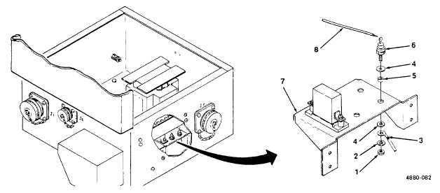
Unsolder wire (8) from terminal of diode (6).
c.
Installation.
(1)
Solder wire (8) onto terminal of diode (6).
(2)
Perform steps (6) and (7) of paragraph 5-11 a.
Figure 5-8. PDU Diode Replacement.
5-11. PDU Terminal Board Replacement. (See figure 5-9.)
a.
Removal.
(1)
Release cover latch and open PDU cover.
(2)
Tag and disconnect all wires from terminal board TB1 (1, figure 5-9). Remove jumpers (2).
(3)
Remove four screws (3) and four self-locking nuts (4) and remove terminal board (1) and
marker strip (5) from PDU housing (6).
b.
Installation.
(1)
Position marker strip (5) and terminal board (1) on PDU housing (6) at location marked TB1.
Fasten with four screws (3) and four self-locking nuts (4) When Installed, screw heads should
be on outside of PDU housing and nuts should be on inside.
5-17