TM 9-6115-647-14&P
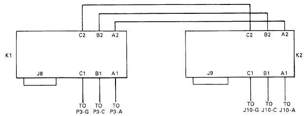
Figure 5-7. PDU Contactor Wiring Diagram.
5-10. PDU Diode Testing and Replacement. (See figure 5-8 ) The PDU has four diodes. Testing and
replacement procedures are the same for all four.
NOTE
When testing or replacing more than one diode, perform complete procedure
on one diode before removing next diode to be tested or replaced.
a.
Testing.
(1)
Release cover latch and open PDU cover.
(2)
Remove nut (1, figure 5-8), lockwasher (2), wire (3), two plastic flat washers (4), spacer (5)
and diode (6) from bracket (7.
(3)
Touch positive multimeter probe to diode terminal and negative probe to diode base and
measure resistance. Resistance should be high.
(4)
Reverse multimeter probe positions and measure resistance. Resistance should be low.
(5)
If multimeter readings were both low or both high in steps (3) and (4), replace diode.
(6)
Install one flat washer (4) and spacer (5) on diode (6). Insert diode into its mounting hole in
bracket (7) and install second flat washer (4), wire (3), lockwasher (2) and nut (1).
(7)
Close and latch PDU cover.
5-16