ARMY TM 9-6115-645-24
AIR FORCE TO 35C2-3-444-12
MARINE CORPS TM 09244A/09245A-24/2
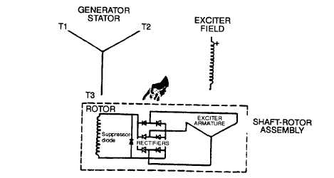
FIGURE 4-10. Brushless Generator Schematic
4-16.4 Rotating Rectifier Assembly. The rotating rectifier bridge consists of rectifying diodes mounted on a brass heat
sink which is in turn mounted on an insulating ring. This assembly also contains a selenium surge suppressor diode which
protects the rectifier diodes from voltage spikes that enter the generator through the main power output cables. The entire
assembly bolts to the adapter on the generator shaft. Therefore, the rotating rectifier assembly will rotate with the exciter
armature eliminating the need for any sliding contacts between the exciter output and the alternator field.
4-16.5 Exciter Field. The exciter field on the high frequency exciter consists of laminated segments of high carbon steel
which are fitted together to make up the field poles. The field coils are placed into the slots of the field poles
4-16.6 Exciter Field Coil Voltage Source. Field coil DC voltage is obtained by rectifying the voltage from a phase to
neutral line of the generator output, or other appropriate terminal to provide the needed voltage reference. The rectifier
bridge is an integral part of the static regulator. The static regulator senses a change in the generator output and
automatically regulates current flow in the exciter field coil circuit to increase or decrease the exciter field strength. An
external adjust rheostat sized to be compatible with the regulator is used to provide adjustnent to the regulator sensing
circuit.
4-16.7 Balance. The rotor assembly is precision balanced to a high degree of static and dynamic balance. Balance is
achieved with the balance lugs on the field pole tips. The balance will remain dynamically stable at speed in excess of the
design frequencies.
4-16.8 Bearing. The generator rotor assembly is suspended on shielded, factory lubricated ball bearings. They are
greased for life and do not require lubrication.
4-16.9 Stator Assembly. The stator assembly consists of laminations of steel mounted in a rolled steel frame. Random
wound stator coils are fitted into the insulated slots.
WARNING
Make sure unit Is completely shut down and free of any power source before at-tempting
any repair or maintenance on the unit. Failure to follow this procedure could result In
Injury or death by electrocution.
4-17
GFNFRATOR ASSFMBLY.
4-17.1
Removal.
a.
Shut down generator set.
b.
Open battery access door and disconnect negative battery cable.
c.
Remove control box assembly, paragraph 2-19.2.
d.
Remove bolts (1 and 4, FIGURE 4-11 ), washers (3) and (5), lockwashers (2) and (6), nuts (7), and rear
housing panel (8) from generator set.
4-26 Change 2