ARMY TM 9-6115-645-24
AIR FORCE TO 35C2-3-444-12
MARINE CORPS TM 09244A/09245A-24/2
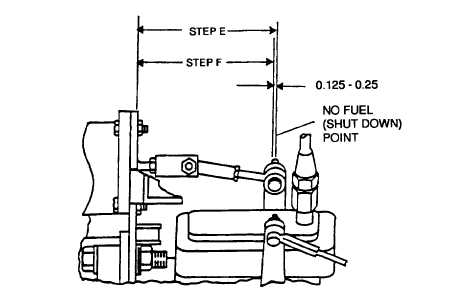
FIGURE 4-9. Governor Actuator Adjustment
SECTION VI. MAINTENANCE OF GENERATOR ASSEMBLY
NOTE
Maintenance procedures for the 50160 Hz (MEP-806A) and 400 Hz (MEP-816A) generators are identical
except where noted.
4-16
TECHNICAL DESCRIPTION.
4-16.1 General. Revolving field type generators have a DC field revolving within a stationary AC winding called the stator.
AC power is distributed from the generator through leads connected to the stator windings. There are no sliding
contacts between the AC winding and the load, therefore, great amounts of power may be drawn from this
generator.
NOTE
Refer to FIGURE 4-10 as needed. To energize the field, DC excitation must be applied to
the generator field coils. The excitation current is supplied from a brushless exciter
mounted on the generator shaft.
The brushless exciter is actually an AC generator with its output rectified through a full wave bridge circuit.
This type of brushless exciter will provide the necessary excitation current.
The generator set field flash circuit, activated during each engine start, applies voltage to the exciter
stator to begin the voltage build-up process to energize the generator field.
The generator output voltage is controlled by controlling the alternating field current. This is accomplished by regulating
the exciter field coil voltage. The exciter field coil voltage is regulated with a solidstate-type voltage regulator.
4-16.2 Damper Bars. Damper bars are inserted through the field laminations and welded at the end to a solid copper
plate. The damper windings provide stable parallel operation, reduce damping current losses, and limit the
increase of third harmonic voltage with increase in load.
4-16.3 Brushless Exciter. The brushless exciter consists of an armature with a three-phase AC winding and rotating
rectifier assembly within a stationary field.
The stationary exciter field assembly is mounted in the main generator frame. The exciter armature is press fit and keyed
onto the shaft assembly. The rotating rectifier assembly slides over the bearing end of the generator rotor shaft and is
secured with bolts and washers to an adapter hub which is shrunk on the generator shaft.
Change 2 4-25


