ARMY TM 9-6115-644-24
AIR FORCE TO 35C2-3-446-12
MARINE CORPS TM 09249A/09246A-24/2
g.
h.
i.
j.
k.
l.
m.
n.
o.
2-66-3
a.
b.
c.
d.
e.
2-66-4
Using multimeter, measure resistance across resistors R6 and R8. Multimeter indication should be between
4750 and 5250 ohms.
Using multimeter, measure resistance across resistors R7 and R9. Multimeter indication should be between
2850 and 3150 ohms.
NOTE
Isolate diode before testing.
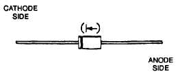
Connect positive lead of multimeter to cathode aide and negative lead to anode side of each diode CR1, CR2,
CR3, and CR4. Refer to FIGURE 2-18. Note ohms indication on multimeter for each diode.
FIGURE 2-18. Diode Identification
Reverse multimeter leads so positive lead is connected to anode side and negative lead is connected to cathode
side of each diode CR1, CR2, CR3, and CR4. Note ohms indication on multimeter for each diode.
Multimeter indications should be 1:10 ratio or greater.
If any indications are other than above, replace defective component.
If no repair is needed, install control box top panel, paragraph 2-15-4.
Raise and secure control panel.
Connect negative battery cable and close battery access door.
Removal.
Shut down generator set.
Open battery access door and disconnect negative battery cable.
Remove control box top panel, paragraph 2-15-1.
Tag and disconnect resistor diode assembly (71, FIGURE 2-14) electrical leads.
Remove screws (70) and resistor diode assembly (71).
Repair.
Repair resistor diode assembly (71, FIGURE 2-14) by replacing resistors (72) and diodes (73).
2-66-5
a. Install resistor diode assembly (71, FIGURE 2-14) and secure with screws (70).
b. Connect electrical Ieads and remove tags.
2-103