ARMY TM 9-6115-643-24
AIR FORCE TO 35C2-3-445-22
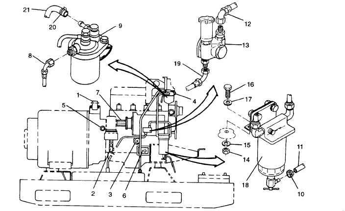
FIGURE 3-13. Right Side Engine Components
al. Disconnect fuel line (8) from engine fuel filter (9). Cap openings.
am. Remove clamp (10) and disconnect hose (11) from fuel filter/water separator assembly (18). Cap openings.
an.
ao.
ap.
aq.
ar.
Disconnect fuel line (12) from fuel transfer pump (13). Cap openings.
Remove nuts (14), Iockwashers (15), bolts (16), washers (17), and fuel filter/water separator assembly(18) from
engine.
Disconnect fuel line (19) from fuel transfer pump (13). Cap openings.
Loosen clamp (20) and remove fuel return line (21) from engine fuel filter (9). Cap openings.
On left side of engine, tag and disconnect electrical Ieads from battery charging alternator (1, FIGURE 3-14), start-
er solenoid (2), starter motor (3), and coolant high temperature switch (4). Move engine electrical harness to rear
of generator set and clear of engine.
as.
at.
Loosen clamp (5) and disconnect coolant drain hose (6) from engine block coolant drain valve (7).
Remove nut (1, FIGURE 3-15), Iockwashers (2), and bolt (3) securing ground strap (4) to skid base.
3-22


