ARMY TM 9-6115-643-24
AIR FORCE TO 35C2-3-445-22
ae.
af.
ag.
ah.
ai.
aj.
ak.
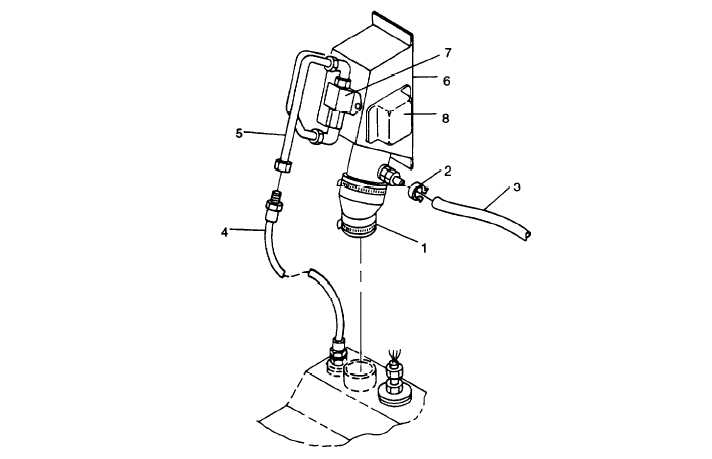
FIGURE 3-8. Fuel Filler Panel Assembly
Remove bolts (1, FIGURE 3-9), Iockwashers (2), battery cables (3), and slave cables (4) from NATO slave recep-
tacle (5).
Remove bolts (1, FIGURE 3-10), Iockwashers (2), and washers (3) securing left rear side panel (4) to skid base.
Remove nuts (8), Iockwashers (6) and (9), washers (7) and (11), and bolts (5) and (10) securing lower left side
panel (12) to front housing and skid base.
With aid of an assistant, remove left rear side panel (4) and lower left side panel (12) as an assembly.
Loosen clamps (1, FIGURE 3-11) and remove air intake hoses (2), (3), and (4) as an assembly.
Loosen clamp (1, FIGURE 3-1 2) and disconnect oil drain hose (2) from engine oil pan.
On right side of engine, tag and disconnect electrical leads from glow plug contactor (1, FIGURE 3-13), low oil
pressure switch (2), oil pressure sender (3), coolant temperature sender (4), magnetic pickup (5), DEAD CRANK
switch (6), and fuel injection pump governor actuator (7).
3-19