e.
f.
9.
h.
i.
j.
ARMY TM 9-6115-642-24
AIR FORCE TO 35C2-3-455-12
MARINE CORPS TM 09247A/09248A-24/2
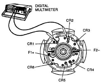
Disconnect F1+ and F2- exciter stator leads from terminal block (13, FIGURE 4-24) or (35, FIGURE 4-25)
in generator end bell. Set multimeter for ohms and connect between disconnected leads. The resistance be-
tween leads should be as shown in TABLE 4-1.
Reading other than shown in TABLE 4-1 indicates open or shorted windings and exciter stator must be re-
placed.
Connect multimeter between each exciter stator field lead and exciter stator lamination. Multimeter reading
of less than infinity indicates defective ground insulation and exciter stator must be replaced.
Connect F1 + and F2- exciter stator leads to terminal block in generator end bell.
Install end bell cover on generator, paragraph 4-11.4, step n (MEP-803A) or paragraph 4-12.5, step g
(MEP-813A).
Connect negative battery cable and close access doors.
4-10.5
FIGURE 4-18. Testing Exciter Field
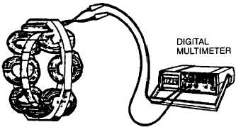
Testing Brushless Exciter Rotor (Armature). Using resistance bridge and multimeter, set for ohms, test the
brushless exciter rotor (FIGURE 4-19) for open or shorted windings and grounds as follows:
FIGURE 4-19. Testing Exciter Armature
4-21


