ARMY TM 9-6116-642-24
AIR FORCE TO 35C2-3-455-12
MARINE CORPS TM 09247A/09248A-24/2
SECTION VII. MAINTENANCE OF GENERATOR ASSEMBLY
4-9
TECHNICAL DESCRIPTION.
4-9.1
General. The generator is a four-pole, revolving field, brushless exciter, reconnectible model of drip proof
construction. The generator rotor is mounted on a center rotor shaft which is supported in the rear by a single ball bearing
mounted in the end bell. The forward end of the rotor shaft is connected to the engine by means of a flywheel and drive
plate. The brushless exciter stator mounts to the end bell while the exciter rotor and rotating rectifier assembly mount
on the generator rotor shaft.
The generator has four wires extending from the stator housing in addition to the AC output leads (FIGURE 4-15).
Lead F1+ and F2- are from the exciter field winding and are connected to the output terminals of the voltage regulator.
Leads Q1 and Q2 are connected to the stator windings and provide reference voltage and input power to the AC voltage
regulator.
FIGURE 4-15. Generator Schematic
4-9.2
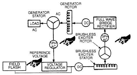
Operation of the generator involves the stator, AC voltage regulator, exciter rotor, exciter stator, a
full wave bridge rectifier, and the generator rotor, FIGURE 4-16. The generator set field flash circuit, activated during the
engine starting process, begins the voltage build-up process. Single-phase AC voltage, taken from one of the stator wind-
ings, is fed to the AC voltage regulator as a reference for maintaining the generator output voltage. AC voltage is converted
to DC in the AC voltage regulator and fed into the exciter stator windings. The exciter rotor produces three-phase AC
voltage that is converted to DC by the rotating rectifier assembly. The resultant DC voltage excites the generator rotor
winding to produce the stator output voltage for the AC load.
FIGURE 4-16. Excitation Block Diagram
4-18 Change 2